Map Sensor
Map sensor means Manifold Absolute Pressure sensor. It can measure the air pressure in the manifold and sent the signal to the ECU.
Test the Map sensor
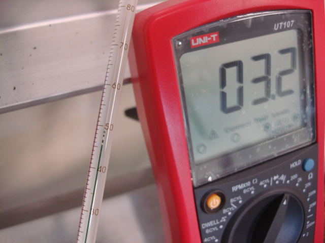
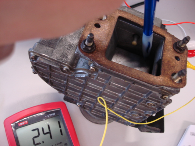
Wire up a map sensor with a 5V feed and earth. Measure the return voltate from the third wire.
 |
| Vacuum Pressure = 0 |
 |
| Vacuum Pressure = 10cm Hg |
 |
| Vacuum Pressure = 20cm Hg |
 |
| Vacuum Pressure = 30cm Hg |
 |
| Vacuum Pressure = 40cm Hg |
 |
| Vacuum Pressure = 50cm Hg |
| Vacuum(cm HG) | 0 | 10 | 20 | 30 | 40 | 50 |
| Voltage(V) | 3.68 | 3.28 | 2.88 | 2.48 | 2.09 | 1.70 |
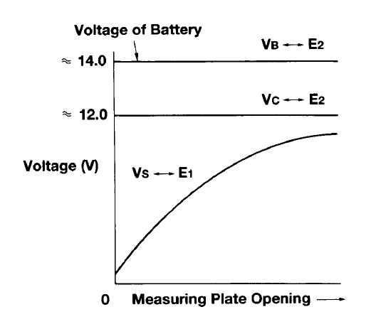
The graph:
The manufacture specifications:
The map sensor match the specification, when the vacuum increase, the voltage output decrease.
The map sensor can read both vacuum and pressure. When the vacuum increase, the voltage output decrease, and when the pressure increase, the voltage output increase.
Explain the internal operation of the sensor and why the output voltage changes.
Here is the internal of the sensor:
When the pressure or vacuum changes, the shape of the silicon chip flexes, and the resistance of the silicon chip changes. There is constant 5V supply on chip and the changing of resistance of chip, when the resistance of the chip (R1) changes, the available voltage after R3 and R1 changes, compared by the opamps and the voltage output to ECU changes.
MAF Sensor
MAF sensor means Mass Air Flow sensor. It measure the mass of air flow through the manifold and sent signal to ECU.
The circuit of MAF sensor show below:
When the air flow through the the MAP sensor, it cools down the thermistor and lows down the resistance of it. So the available voltage after thermistor increased. This voltage goes to the non inverting terminal of the opamps and compare the available voltage after the hot wire and turn on the power transistor to let current through. The current flow through the thermistor and heat it up back to base temperature and also flow through the hot wire to increase the available voltage after it, that is the voltage output signal to the ECU.
The Specification of the MAF sensor:
When the airflow increased, the output voltage increased.