Monday, June 27, 2011

ABS On Car

On car exercises
A: brake booster  B: brake fluid level switch  C: brake master cylinder

RPM sensor

ABS control unit, ABS modulator, ABS pump

Wheel speed sensor

Parking brake switch under the plastic cover

Foot brake switch

Main ABS control unit fuse

ABS Wheel Speed Sensor
This wheel speed sensor is inductive type, it has 2 wires, one for "+" signal and one for "-" signal. If it gives digital signal, it should has 3 wires, reference, ground and signal out.

Measure the air gap
Specification:

Right Front:
 The air gap is 0.254mm + 0.305mm = 0.559mm

Left Front:
The air gap is 0.356mm + 0.305mm = 0.661mm

The gap of front wheel speed sensors are all in specification.
The rear wheel are drum brake, can not measure the gap easily. We should take off the drum.

The waveform:
This is analogue pattern at 20KM/h, because it is inductive type sensor.

Use the frequency scale on multimeter. Turn the wheel at promixally the same speed as in the above test.
The frequency is 216Hz at 20KM/H
From the pattern: 4ms per circle, so the frequency is 1s / 0.004s = 250Hz.
It is close to the reading of multimeter, because we can not control exactly the same speed for both testing.

Using a Scan Tool
We jack up the car on the hoist.
ABS live data:
When the vehicle is running at high speed: 


When the vehicle is stopped:

The D.T.C:
This vehicle is front wheel drive. We jack it up on the hoist, the rear wheel can not turning as the front wheels, so there are no signal from both rear wheel speed sensors and create faults.

Actuator test:


When we click the Start button for testing, we can hear the solenoid works, so this circuit should be fine.(The clicking sound from the video) We can test other circuit and actuator by the same way. But this is only for test electronic circuit or components, not for pressure, brake fluid, brake hose or anything else. 

Antilock Braking System Bench Test

 ABS components:
1. brake rotor  2. wheel speed sensor  3. wheel speed sensor rotor  4. ABS module  5. brake master cylinder  6. caliper  7. booster

Wiring diagram practice:


The colour code of wires:

Using the wiring diagram in the workshop manuals identify the wheel speed sensors and list their wire colours for each sensor:
Front right: Black(+) White(-)
Front left: Red(+) Green(-)
Rear right: Yellow(+) Brown(-)
Rear left: Blue(+) Pink(-)

In the ABS wheel speed sensor, the braded wire is grounded wire, it is used to stop the EMF to effect the signal in the sensor wire.

The fuses in the ABS circuit:
1. FL main 3.0w  2. ASB 50A  3. Gauge 10A  4. Dome 20A  5. Stop 15A  6. ECU-1G 15A

The earth wire colours and pin numbers of ABS control unit and ABS motor:
ABS control: Pin 10 and 7( White-Black )
ABS motor: Pin 1( White-Black )

On the wiring diagram for the ABS actuator, identify which solenoids control which wheel cylinder.
Front Right Wheel: Pin 2(Red-White), Pin 6(Red-Green)
Front Left Wheel: Pin 3(Blue-Red), Pin 7(Blue-White)
Rear Right Wheel: Pin 4(Green-Black), Pin 8(Green-Yellow)
Rear Left Wheel: Pin 1(Brown-White), Pin5(Brown-Red)

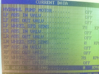
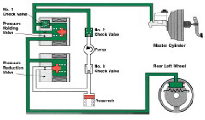
Inlet and outlet valves:

Normal Braking:
Inlet valve open and outlet valve close

Pressure Reduction:
Inlet valve close and outlet valve open

Holding the pressure:
Inlet valve close and outlet valve close

Increase the pressure:
Inlet valve open and outlet valve close, the pump operate to increase the pressure in the system.

There are three main types of wheel sensors on modern vehicles. One sends an analogue signal using and inductive pick up, the others send a digital signal using ether hall effect or magnetoresistant encoder.

On the graph below draw a digital signal that switches 5 volts every 2 seconds.
Mark volt and time scales on graph that will show the signal well.

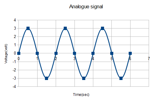
On the graph below draw an analogue signal with a frequency of 0.5 Hz and a maximum of +3 volts. Mark volt and time scales on graph that will show the signal well.
Frequency is 0.5 Hz. T=1/0.5Hz=2Sec


ABS Demonstrators


Locate the wiring diagram for your demonstrator vehicle. Find the ABS wheel speed sensor pin out connections to the ECU on the wiring diagram and the demonstrator. Record which ECU wires go to which wheel speed sensors:
Left Front  B19 ECU Pin# 4 and 5
Left Rear   B21 ECU Pin# 7 and 9
Right Front B20 ECU Pin# 11 and 21
Right Rear  B22 ECU Pin# 24 and 26
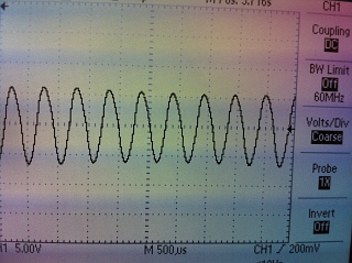
This is inductive type speed sensor, the principle is same as the inductive RPM sensor, RPM sensors

The waveform:
Left Front:

Left Rear:

Right Front:

Right Rear:

The waveforms are not exactly same. the peak voltage is different because the gap between the sensor and teeth of the rotor is different. Small gap, high voltage and big gap, low voltage.

The gap:

Measure AC voltage:
Left Front: 4.7V

Left Rear: 3.3V

Right Front: 15.1V

Right Rear: 5.2V

The multimeter can not be accrate as the oscilloscope, the signal frequency too fast to pick it up, the multimeter shows the RMS reading(the peak voltage X 0.707) of the signal. The oscilloscope waveform can show us the peak voltage, frequency, duty circle, peak to peak voltage.

ABS Relays
Record the name of the relay or switch that powers up the ABS ECU: 
K39 Protection Relay

Record the name of the relay or switch that powers up the ABS pump: 
K100 Pump Motor Relay

Record the name of the relay or switch that sends power to the ABS HCU solenoids: 
K38 System Relay

Relay wire identification:
What is the ECU pin number for the wire that brings in the power to the ABS ECU?
Pin #1 of ECU

What is the ECU pin number, or other number, for the wire that controls the relay for the ABS ECU?
Line #15, Pin #86 of relay


What is the pin number for the wire that brings in the power to the ABS Pump?
Pin #13 of hydraulic control unit

What is the pin number, or other number, for the wire that controls the relay for the ABS Pump?
Pin # 11 of hydraulic control unit

The waveform:
ABS pump relay VS ABS pump
1: Relay
2: Pump
A: the key is on
B-C: Self testing, relay is on, voltage supply to pump and pump works
C-D: Relay is off, no power to pump and pump stop to work, but the inertia keep the pump running for a short time and create EMF
D: the key is off
D-E: Relay is on a while after the key is off for safey, the pump works again
E: Relay is off
F: No power in the system.

The solenoid relay VS the solenoid
A: the key is on
B-C: self testing, relay is on and solenoid is working
C: relay is off
D: the key is off

The solenoid:
Pin #3
A: the key is on
B: the key is off
When the key is on, the solenoid on and off for self testing then keep it on until the key is off, then pulse open and close the valve 25-40 times to release the pressure and safey.


When the ABS system is working, the pump increase pressure in the break system, and solenoids open and close the valves to reduce and hold the pressure.

Monday, June 13, 2011

Input Sensors and Actuator On-Vehicle

1. Battery Voltage to Injectors

The battery voltage to injector of cylinder 1 is 14.38V
The injector is a solenoid, when current flow through the coil, creates the magnetic field to open the injector and spray the fuel. The fuel injector is earth triggered, the battery voltage supply to the injector all the time, the signal from ECU switch on or off the transistor to close or open the injector circuit. If the battery voltage is low, the current in the solenoid is low, the magnetic field may not strong enough to full open the injector.

The circuit diagram of EFI


2. Reference Voltage at TPS sensor
The reference voltage at TPS sensor is from ECU, it like a power supply to TPS sensor, when the throttle opened in different angle, the signal voltage changes, because the resistance changes, ECU will know how much the throttle opened. If the reference voltage is wrong, the engine will get the wrong signal voltage.
The reference wire between ECU and TPS will cause the problem of the reference voltage.
If it short to ground, the reference voltage will very low.
If it open circuit, no reference voltage to TPS.

3. Ground at TPS sensor
The voltage on ground terminal is 4.2mV, less than 0.05V, it is good earth.
If it is the bad earth, the total resistance in the TPS sensor will change, and the signal voltage should be wrong. See WS3A - Oscilloscope Patterns to Capture  for detail.
The corrosion, bad connection, broken wires can cause the bad earth.


4. TPS sensor return/output
The throttle is closed, signal voltage is 0.370V

The throttle is half way opened, signal voltage is 2.050V

The throttle is fully opened, signal voltage is 3.67v
Slowly open the throttle from closed to full open:
The TPS works fine, no sudden jumps or gaps in the signal.

Idle swith:
 
The colour of  idle switch wire is Blue
The idle switch works fine. The battery voltage supply to the idle switch wire for this TPS. When the throttle is closed, the switch is closed and make a circuit to ground, so the voltage is low. When the throttle opened, the switch opened and the circuit opened to ground, so the voltage is battery voltage.


The principle of TPS sensor see Sensors - TPS for detail.


Bad earth, wrong reference voltage, the corrosion all can make the TPS signal out faulty.


The circuit diagram of TPS sensor:


5. TPS switches
Idle wire colour: Black

Volts at idle is 0.07V

Volts at part throttle or open throttle is 10.78V

Volts at open throttle is 0V
The wire diagram of the TPS switch
When the engine runs at idle, the battery terminal contact to idle terminal, so the voltage of idle is battery voltage and voltage of psw is 0V.
When the parts throttle cruise, PSW and Idle both no contact with the battery terminal, the voltage of them both are 0V
When wide open throttle, the battery terminal contact to PSW terminal, so the voltage of psw is battery voltage and voltage of Idle is 0V.


ECT (Engine Coolant Temperature) Sensor
The engine is warming up. The normal operation
The reading of ECT sensor is 2.66V, the engine is still cold. The normal operating voltage of ECT should be about 0.5V.

After a few minutes, the reading of ECT is 2.49V. That means the resistance of ECT is decreasing and engine is warmer than before.

The principle of ECT see Sensor - CTS for detail.

The ECT gives the signal to ECU let it know the engine temperature. If the temperature is low, the ECU will open the injector for longer to spray more fuel that warm up the engine until the engine reach the normal operating temperature.
Bad earth, corrosion of the wire or terminals, broken wires can make the ECT gives the wrong signal to ECU.

7. Ground Coolant Temperature Sensor
The ECT grond voltage is 0.02V less than 0.05V, it is good earth.
Bad earth will change the resistance of ECT to gives the wrong signal to ECU.
If the ECT has the bad earth, the signal voltage should higher than normal, see WS3A - Oscilloscope Patterns to Capture for detail.


The circuit diagram of ECT:

RPM Sensor or Crank Position Sensor (CKP)
The reading of the CKP is 0.29V (AC) at idle speed

Increase RPM to 2500 rpm, the reading is 0.56V (AC)

Change to DC volts, the reading is 0.568V (DC) at idle speed

Increase RPM to 2500 rpm, the reading is 1.08V (DC)

Change to read Hz, the reading is 503Hz at idle speed.

Increase RPM to 2500 rpm, the reading is 1539Hz.

The principle of RPM see Speed or Position Sensors for detail.

The best showed if RPM sensor was working is Hz. The signal of CKP is analog signal like wave signal. The different engine speed will change the frequency of the signal. The best way to measure the signal is using oscilloscope. But if oscilloscope is unavailable, then using multimeter to measure the frequency and duty cycle.

RPM sensor use to adjust the firing time, wrong sigal can cuase misfire and engine stall.

The circuit diagram of RPM:

MAP or MAF Sensor
MAP:
When turn the key ON, but don't start the engine, the reading of MAP sensor is 1.79V

When the engine at idle speed, the reading of MAP sensor is 0.39V

Short acceleration, the maximum reading of MAP sensor is 1.46V

The principle of MAP sensor see Sensor - MAP, MAF for detail.

The reading above is correct. When the engine is not running, the vacuum in the manifold is minimum, the reading should be the highest. When the engine at idle speed, the vacuum in the manifold in maximum, the reading should be lowest. When acceleration, the vacuum in the manifold decreased, the reading should be increased.

If the ECU get the wrong signal from MAP sensor, the injector open time will be wrong, the air / fuel ratio will be wrong, the engine will run rich or lean.

The circuit diagram of the MAP sensor:

MAF:
Check the terminals:
Pin 1 is temperature sensor voltage

Pin 2 is battery voltage.

Pin 3 is ground

Pin 4 is reference voltage

Pin 5 is MAF signal out
Set multimeter to Hz scale and turn on the key:
The reading is 0 Hz

Start the engine, let it idle
The reading still 0 Hz.

Short acceleration:
The reading of MAF Hz increased.

The principle of MAF sensor see Sensor - MAP, MAF for detail.

The reading of this MAF is correct. When the key is on and running at idle speed, the air flow is stable and signal voltage is stable, so the frequency is 0 Hz. When short acceleration, the signal voltage changes so the frequency increase.

Wrong signal cause the same problem as MAP sensor.

IAT, ACT or MAT
The reading of IAT sensor is 3.21V. The reading is more than ECT before and shows IAT sensor is colder than ECT. Because IAT and ECT are both NTC resistor.

The principle of IAT see Sensor - IAT for detail.

Higher the air temperature, the reading of IAT is lower. Same volume of high temperature air contain less O2 atom than low temperature air. When the reading is high, means low temperature air, more O2 atom, so ECU control injector spray more fuel to reach 14.7:1 A/F ratio.
When the faulty signal is higher than normal, the mixture will be Rich.
When the faulty signal is lower than normal, the mixture will be Lean.

The circuit diagram of IAT:

Camshaft Position Sensor (CMP)
At idle:
DC voltage reading is 0.06V

AC voltage reading is 0.4V

Hz reading is 46Hz

Duty cycle reading is 66.9%
The best way to measure the CMP signal is oscilloscope, because it is analog signal. If don't have oscilloscope, the measure Hz by multimeter, it tells you how fast the camshaft turning, measure the duty cycle, it tells you the percentage of the signal voltage is positive of negative.

The circuit diagram of CMP: