Thursday, July 7, 2011

Electronic Transmissions and Scan Tools

PCM = Powertrain Control Module
TCC = Torque Converter Clutch
TPS = Throttle Position Sensor
ECT = Engine Coolant Temperature Sensor
VSS = Vehicle Speed Sensor
PSA = Transmission Range Fluid Pressure Switch Assembly
TTS = Transmission Temperature Sensor.

For Holden 4L60-E Transmission:
Block Diagram for transmission:

The powertrain control system:

The shift chart:
When the vehicle is shifted into Drive and starts out in first gear, the shift solenoid 1-2 and 2-3 are both ON.
When the vehicle automatically shifts into second gear, the shift solenoid 1-2 is OFF and 2-3 is ON.
When the vehicle automatically shifts into third gear, the shift solenoid 1-2 and 2-3 are both OFF.
When the vehicle automatically shifts into fourth gear, the shift solenoid 1-2 is ON and 2-3 is OFF.

If no solenoids can came ON, the vehicle still can drive but it will stay in third gear, the speed may not go over 40 km/h, and it can climb the hill if the engine is powerful enough,that is the fail safe.

Code:
DTC 24: No vehicle speed signal
This code may caused by faulty ECU, faulty PROM(Programmable read-only memory) or an incorrect PROM,bad connection of the VSS sensor.
For diagnosis the code.
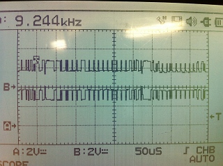
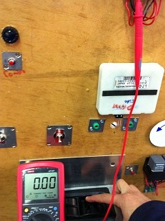
Check the VSS sensor by oscilloscope, if the sensor gives the signal when the wheel is turning, the sensor is working good, then test the continuity between VSS sensor and ECU. The voltage drop should be lower then 0.05V. IF the connection is good, then check the ECU and PROM.

DTC 14: ECT signal voltage is low
This code may caused by faulty ETC sensor, bad connection of ETC sensor.
For diagnosis the code.
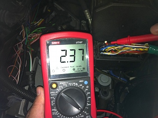
Check voltage across the two terminals of the ECT sensor by multimeter, if the voltage decrease as the engine temperature increase, and it about 0.5V after the engine is already warmed up, the ECT sensor and connection are good. If the it is not, test the connection between ECT sensor and ECU and ECT sensor resistance.

On-Car Exercises:
When the O/D is off:
When the O/D is off, the transmission can not goes to 4th gear, because the 4th gear ratio is about 0.8 : 1
When the vehicle at 3rd gear and engine at 2050 RPM. The torque converter clutch lock up solenoid is on to lock up the turbine and flywheel and make the input speed of transmission same as the engine speed.

When O/D is ON:
The vehicle can shift to 4th gear now and torque converter clutch lock up solenoid is on at 1600RPM at 4th gear.

When the driver apply the feet on the brake pedal and slow down the vehicle, the torque converter clutch will disengage, flywheel and turbine are disconnected.

The chart:

Tuesday, July 5, 2011

CAN - Multiplexing

Range Rover 2003-2004
Can communication twisted lines:
These are yellow/black and yellow/brown CAN communications twisted lines from ABS ECU.

The pattern:
The base voltages of H-CAN and L-CAN are both 2.8V and time division is 50us.
Channel A: Yellow/Black wire. The signal voltages increased from 2.8V to 3.6V. It is H-CAN.
Channel B: Yellow/Brown wire. The signal voltages decreased from 2.8V to 1.6V. It is L-CAN.

Those two channel signals are opposite to each other and have same 2.8V base voltage, the differential amplifier compares those two channels and create the digital signal. When the signals are at 2.8V for both channel, the different between those signal is 0V and gives ECU digital talk as 0. When the H-CAN channel is 3.6V and L-CAN is 1.6V, the difference between those channels is 2V and gives ECU digital talk as 1.
The internal clock is counting how long the digital signal stay on and gives the code:
ECU read the codes and know the information they are carried, and the CAN system can transport the information between different units and systems.

Measuring by multimeter:

The voltage reading gives from the multimeter can not show us the signal is switching, because the signal is switch too fast to carry by the multimeter, the multimeter gives us the RMS reading instead. So the oscilloscope is the best choice for measuring the CAN system signal.

Scan Tool:
The scan tool show us the menu of the central body electronics CAN system:

For testing the output and communication, we use the scan tool as a input the system, click Actuations and show us the function we can test:

We tested the front wiper:
The wiper is working so the output and communication is good. If there is a fault in the wiper system, it should be the input.

The central body control system including the wiper, central locking, interior light on/off and etc are controlled by low speed CAN, because they are for convenience do not need fast response time. But for ABS, SRS, engine control system and etc, they are high speed CAN system, because they are important and need fast response time.

Wiring diagram
The wiring diagram of Honda accord

The door multiplex control unit and climate control unit is low speed system and ABS/TCS is high speed system.
The gateway show below:
The pin23 and 24 are from high speed CAN system and pin 25 is to the low speed system. The gateway changes the signal to different speed, it between different speed systems.

Sleep mode:
After awhile of all output components are off, the system will goes to sleep mode to saving the battery energy, store the memories, and receive the signal from the remote control or key to wake up the system. In the sleep mode, the system will drawn much lower current than the normal operation, it is about 30mA. For example, we can wake up the central locking system to unlock the door, wake up the engine management system to start the engine by the remote control when we are heading to the vehicle. Any operation of input can wake up the system.
The video show the Range Rover goes to sleep mode:
The ABS H-CAN and L-CAN voltage stay at about 0.4V when the system goes to sleep mode after about 2-3 seconds everything been shut off, and no talking when it is in sleep mode.

Saturday, July 2, 2011

Honda Multiplexing Board

The wiring diagram:

Communication Lines:
The communication line between door unit and driver unit is brown colour and pin #A15(door), #2(driver)
The communication line between driver unit and passenger unit is pink colour and pin #B1(driver), #9(passenger)

Earths and Voltage supply lines
Door Unit: Earth - A12 A19 Black,  Voltage supply - A1 pink
Driver Unit: Earth - A14 B11 Black,  Voltage supply - A1 white/black A12 pink A24
Passenger Unit: Earth - A8 B22 Black, Voltage supply - A22 yellow, A24

Create Fault:


The driver side rear window can goes up but can not goes down and relay does not switch, there is no click sound from the relay when switch down the window.

Analyze the fault
The connection between passenger unit to the relay may open circuit. The rely may not working. The door unit may not gives the signal to roll down the window.

Test mode 1:

The D.T.C of test mode 1:

The test mode 1 can not give us the D.T.C, that because this fault is not on the map of the test mode 1.

Check the open in the wire:
This is for communication test.
The specification:

Door unit to driver unit:
The voltage is 7.57V

Driver unit to passenger unit:
The voltage is 7.57V

The voltages are all in spec, so the wires of communication are good.

Test Mode 2:
Put the system to test mode 2 to test the inputs

Switch the input, if you can hear the sound, that means input are working fine.
The window switches inputs are all good.

For this fault, input and communication are all good, so the faults should be from the passenger unit to the window roll down relay.

Relay Check:
The voltage supply:
The voltage supply to the relay is 12.06V. It has the power to switching

the control circuit check.
There is no voltage to the control terminal of the relay, the control circuit is open circuit. That means the wire between the passenger unit and relay control terminal is broken.

Friday, July 1, 2011

Controlled Area Network Board

Controlled Area Network Board

The pattern of H-CAN and L-CAN
A: the pattern starts
B: the pattern finishes
Channel 1 is the H-CAN, because the voltage increase from the base voltage.
Channel 2 is the L-CAN, because the voltage decrease from the base voltage.
The difference between H-CAN and L-CAN base voltage the ECU marks it at 0 in the digital signal and the difference between increased voltage of H-CAN and decreased voltage of L-CAN is 1 in the digital signal. 

The patterns:
Right indicator:

Left indicator:

Rear wiper:

Stoplights:

Fuel pump:

Reverse lights:

In the red square, the different signal gives different commands to the control unit.

The circuit of the board:


Right hand indicator:
input pin #7 -> R5 -> Pin #6 (VP18F258) -> CAN -> IC5 -> Control unit pin #5 -> R32 -> IC9 -> U7 (transistor) -> output pin #5
Rear Wiper:
input pin #9 -> R8 -> Pin #25 (VP18F258) -> CAN -> IC5 -> Control unit pin #10 -> R35 -> U14 (transistor) -> RL4 (Relay) -> output pin #8

Voltage regulators:
U1 7805
input pin #1,2
output: Pin #1 (VP18F258) through R20, Pin #20 (VP18F258), Pin #3 (IC4), Pin #16 (IC3)

U2 7805
input pin #1,2
output: Pin #14 (output control unit)

For stoplight:
when the vehicle wants turn on the stoplights, current go through input pin#5, R3 to the pin #4 of VP18F258 to translate the signal to digital H-CAN signal and L-CAN signal through IC4. The CAN signal goes to IC5 and translate to output control unit. The unit will sent the signal from its pin #3 go through R20 to IC7 to switch on the transistor U5 to closet the circuit and turn on the stoplights from output pin #3.