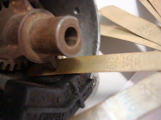
1. Obtain an electronic inductive distributor.
2. Visually inspect condition
3. Test ignition primary amplifying module for serviceability
4. Test pickup coil for serviceability.
Check the resistance:
 |
| NE pickup coil R=478R |
 |
| G pickup coil R=245R |
G Pickup Coil 185-275R. NE Pickup Coil 370-550R
So, it is serviceable.
Check the Air Gap:
 |
| G pickup coil Air Gap=0.305mm |
 |
| NE pickup coil Air Gap=0.356mm |
G pickup coil Air Gap=0.2-0.4mm NE pickup coil Air Gap=0.2-0.4mm
so, it is serviceable.
The waveform on digital oscilloscope:
A: The reluctor tip begin close to the pickup coil
B: The reluctor tip closest to the pickup coil
C: The reluctor tip moves away from the pickup coil.
The shape of the wave depends on the shape of the reluctor tip. When the reluctor tip close to the pickup coil, it cut through the magnetic field of it, so the voltage been created in the pickup coil. When the tip pass away the point of the coil, the current changes the direction(back EMF), so the voltage goes to negative.
The Hall-Effect sensors:
Check the degrees turned and voltage:
Connect the distributor to the power supply and check the voltage
0 degree |
45 degrees |
90 degrees |
135 degrees |
140 degrees |
175 degrees |
180 degrees |
The Waveform:
A: The big tooth contact to the magnetic field.
B: The big tooth dis-contact to the magnetic field.
C: The period between two teeth contact to the magnetic field.
When the big tooth of the semi conductor contact to the magnetic field, it creates hall voltage to the opamps and let current through to switch on the transistor to gives the signal out to ECU.
Optical distributor:
Wire up the distributor and observe the wave form
When the interrupter block the beam to the photo electric cell, the output voltage is supply voltage, and when the interrupter moves away, the output voltage is low voltage.
The waveform shows blew:
When the beam to the photo diode, the diode like a conductor and let the current in 22k resistor circuit through it to the ground, so the output voltage is nearly 0V, then the beam has been blocked, the diode like insulator, the output voltage should be the supply voltage.
Hall-effect, optical sensor give the digital signal to the ECU, but inductive sensor gives the analogue signal. These sensors are normally connected to the cam shaft, and the speed of cam shaft is half of the crank shaft. So, when crack shaft turned 2 rotations, these sensors are one rotation.


Nice to see some understanding of the concepts demonstrated.
ReplyDelete