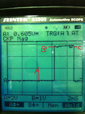
| Signal Name | RPM Sensor |
| Volt/Division/Range | 5V |
| Time/Division/Range | 2ms |
The pattern show below:
A: When the tip close to the coil, cut the magnetic field and build up the voltage in the wiring.
B: When the tip begin moves away form the point of the coil.
B-C: Back EMF.
By gives the signal to ECU, the ECU can find out the engine speed and crank shaft angle.
RPM CAM Sensor
| Signal Name | CAM Sensor |
| Volt/Division/Range | 2V |
| Time/Division/Range | 100ms |
The pattern show below:
A: When the tip close to the coil, cut the magnetic field and build up the voltage in the wiring.
B: When the tip begin moves away form the point of the coil.
B-C: Back EMF.
There are 3 peaks of the voltage, there are indicate TDC of cylinder 3,4 and 2. So ECU can find out when is the cylinder 1 at TDC and control and firing time.
Injectors
| Signal Name | Injector |
| Volt/Division/Range | 10V |
| Time/Division/Range | 5ms |
The pattern show below:
A: Injector is closed.
B-C: The circuit grounded and current through the coil and injector is opened.
C: Injector closed.
C-D: Back EMF.
This injector is earth triggered, and control by PWM from ECU. ECU increase the injector open time when need for fuel and decrease the time when less fuel needed.
Idle air
B-C: The circuit grounded and current through the coil and injector is opened.
C: Injector closed.
C-D: Back EMF.
This injector is earth triggered, and control by PWM from ECU. ECU increase the injector open time when need for fuel and decrease the time when less fuel needed.
Idle air
| Signal Name | Idle Air Control |
| Volt/Division/Range | 10V |
| Time/Division/Range | 100ms |
The pattern show below:
There are two channels of PWM signal from ECU to control the IAC. Each signal control one coil and create the magnetic field. The shaft of control valve in the middle of two coils. By changing the PWM voltage, two coils creates opposite magnetic field and turn the shaft to control the valve open or close. So those two signals are opposite. Open more when the engine load increased.
Ignition timing control (digital)
| Signal Name | Ignition |
| Volt/Division/Range | 2V |
| Time/Division/Range | 2ms |
The pattern show below:
A: no signal
B-C: ignition time.
This is digital ignition timing control, ECU gives the signal to turn on the ignition by switch on the transistor to complete the circuit.
Oxygen sensor
| Signal Name | O2 Sensor |
| Volt/Division/Range | 0.5V |
| Time/Division/Range | 1sec |
The pattern shows below:
When snap on the engine, the engine running very rich and signal voltage of O2 sensor raise up to 0.9V, and then back to normal. This O2 sensor of the engine wire up in different way and with aftermarket ECU, so the signal voltage at idle speed is not normal.
Ignition Primay
Ignition Primay
| Signal Name | ignition primary |
| Volt/Division/Range | |
| Time/Division/Range |
The pattern:
A-B: The dwell time, the primary coil grounded and closet the primary circuit, current flow through the coil to charge up the magnetic field.
C: When the primary coil disconnect to the ground, the magnetic field of the primary coil collapse and create very high voltage to jump cross the gap of the spark plug, that is the fire voltage.
C-D: After the voltage jump cross the gap, the rest of energy just hold it for a while, that is the burn time.
D-E: The coil oscillatory.
For this pattern, in the dwell time, the voltage raised up a bit, that means there is some resistance on the earth side of the coil.


No comments:
Post a Comment