Identify the capacitor


This is Non-electrolytic capacitor, no polarity requirements, it can take high voltage.


This is electrolytic capacitor . The terminal which is marked "-" is negative. The polarity must be corrected in circuit. It has leakage current.

This is tantalum capacitor. It is physically smaller and lower leakage.


This is variable capacitor, it can adjust the capacitance.
EIA code
EIa code is shown the capacitance of the capacitor. It consists 3 numbers. To identify the capacitance, write down first 2 numbers, then add numbers of zero as the third number shown.i.e: EIA code is 105. the capacitance is 5 zero after 10, it is 1,000,000F
Charge Time
Capacitors take time to charge, to calcualte the time, the formula is T=RxCx5. R is the resistance in the circuit, C is the capacitance of the capacitor.
Capacitor charged 2/3 applied voltage in first 1/5 time of charging, then the speed of charging slow down.
Exercise
Build the circuit show as below, calculate and observe the charge time of the capacitor.

1. C=100uF R=1Kohm
Calculation: T=5xRxC= 5 x 1000ohm x 100 x10(-6)F = 500mS
2. C=100uF R=0.1Kohm
Calculation: T=5xRxC= 5 x 100ohm x 100 x 10(-6)F = 50mS
3. C=100uF R=0.47Kohm
Calculation: T=5xRxC= 5 x 470ohm x 100 x 10(-6)F = 235mS
4. C=330uF R= 1Kohm
Calculation: T=5xRxC= 5 x 1000ohm x 330 x 10(-6)F = 1650mS
Observation:
Bulit the circuit on breadboad:

1. C=100uf R=1Kohm

T=500mS
2. C=100uF R=0.1Kohm

T=50mS
3. C=100uF R=0.47Kohm
T=250mS
4. C=330uF R= 1Kohm

T=250ms x 7 =1750mS
Circuit 1,2,3 have same capacitor, but different resistor. R1>R3>R2, T1>T3>T2
Less resistance in the circuit, less charging time for same capacitor.
Circuit 1 and 4 have same resistor, but different capacitor. C4>C1, T4>T1
Less capacitance in the circuit, less charging time for same resistance.
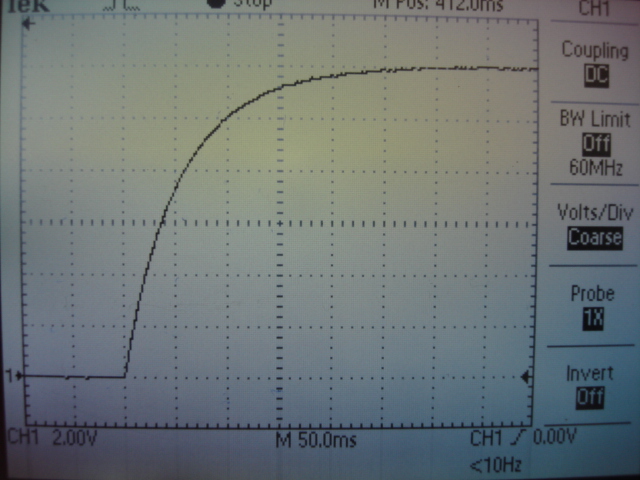
Capacitor charge about 63% in first 1/5 of total charge time, and then slow down the speed of chargeing, so the graph shows a curve.
Again very good work, good explanations, if you could add why the graph curves it would be even better
ReplyDelete