Can communication twisted lines:

The pattern:
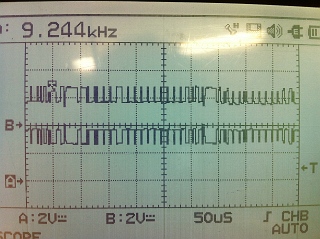
Channel A: Yellow/Black wire. The signal voltages increased from 2.8V to 3.6V. It is H-CAN.
Channel B: Yellow/Brown wire. The signal voltages decreased from 2.8V to 1.6V. It is L-CAN.
Those two channel signals are opposite to each other and have same 2.8V base voltage, the differential amplifier compares those two channels and create the digital signal. When the signals are at 2.8V for both channel, the different between those signal is 0V and gives ECU digital talk as 0. When the H-CAN channel is 3.6V and L-CAN is 1.6V, the difference between those channels is 2V and gives ECU digital talk as 1.
The internal clock is counting how long the digital signal stay on and gives the code:

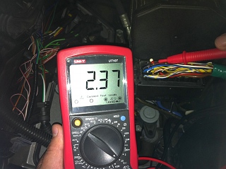
Measuring by multimeter:

Scan Tool:
The scan tool show us the menu of the central body electronics CAN system:

For testing the output and communication, we use the scan tool as a input the system, click Actuations and show us the function we can test:

We tested the front wiper:
The wiper is working so the output and communication is good. If there is a fault in the wiper system, it should be the input.
The central body control system including the wiper, central locking, interior light on/off and etc are controlled by low speed CAN, because they are for convenience do not need fast response time. But for ABS, SRS, engine control system and etc, they are high speed CAN system, because they are important and need fast response time.
Wiring diagram
The wiring diagram of Honda accord


The door multiplex control unit and climate control unit is low speed system and ABS/TCS is high speed system.
The gateway show below:

Sleep mode:
After awhile of all output components are off, the system will goes to sleep mode to saving the battery energy, store the memories, and receive the signal from the remote control or key to wake up the system. In the sleep mode, the system will drawn much lower current than the normal operation, it is about 30mA. For example, we can wake up the central locking system to unlock the door, wake up the engine management system to start the engine by the remote control when we are heading to the vehicle. Any operation of input can wake up the system.
The video show the Range Rover goes to sleep mode:
The ABS H-CAN and L-CAN voltage stay at about 0.4V when the system goes to sleep mode after about 2-3 seconds everything been shut off, and no talking when it is in sleep mode.
No comments:
Post a Comment