Signal Name | MAP Sensor |
Volt/Division/Range | 0.5V |
Time/Division/Range | 5sec |

A: When started acceleration.
A-B: Vacuum in manifold decrease and signal voltage increase.
B: When started deceleration.
B-C: Vacuum in manifold increase and signal voltage decrease.
C: Snap on the engine, the vacuum in the manifold will increase very high when suddenly decelerate, and signal voltage is very low.
Bad earth will cause the MAP sensor operate incorrectly, because bad earth gives high resistance on the earth side and signal voltage incorrect.Show as below:


When MAP sensor has a bad earth, when throttle opened big angel, vacuum is low, and signal voltage only has 2V.
When MAP sensor has bad earth, the pattern will like show below:

When the MAP sensor has bad earth and gives low voltage signal than normal to ECU. ECU will short the injector open period, and don't have enough fuel for combustion, the engine will run lean.
TPS
| Signal Name | TPS Sensor |
| Volt/Division/Range | 0.5V |
| Time/Division/Range | 2sec |

A: Throttle is closed
A-B: Throttle is opening and signal voltage increasing
B-C: Throttle is closing and signal voltage decreasing
C: Throttle is closed again.
Bad earth will cause the TPS sensor operate incorrectly. The reason show below:

When the TPS sensor is working fine. The throttle is closed, the signal voltage is 0.5V.

When the TPS sensor is working fine. The throttle is half way opened, the signal voltage is 2.5V.

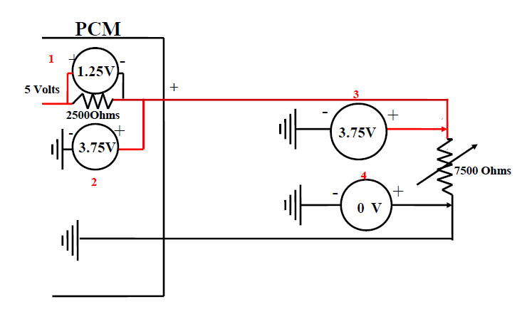
When the TPS sensor has bad earth, 7KR for example. When the throttle is half way opened, the total resistance is 5KR+7KR=12KR, the current is 5V/12KR=0.417mA, V4=0.417mA x (7KR + 2.5KR)=3.96V.
When TPS sensor has bad earth, the pattern will like show below:

When the TPS sensor has bad earth and gives high voltage signal than normal to ECU. Let ECU think the throttle is opened more than the fact, and spray more fuel makes the mixture rich.
ETC
| Signal Name | ECT Sensor |
| Volt/Division/Range | 0.5V |
| Time/Division/Range | 2sec |

The engine temperature change very slowly that the ECT sensor signal looks like a straight line.
When the ECT sensor works fine:
 |
| When engine is cold. Signal voltage = 3.75V |
 |
| When engine is warm. Signal voltage = 0.5V |
Faults:
1. Bad earth. High resistance on earth side:

The total resistance in the circuit increased, so the current decreased. The voltage across the pickup resistor decreased,and the available voltage after pickup resistor (signal out) increased.
The faulty pattern show below:

2. Open circuit:
 |
| open circuit between ECU and ECT sensor |
 |
| open circuit in ground |
The faulty pattern show below:

When the ECT signal voltage is higher than the normal condition, it gives wrong signal to ECU and let it thought the engine is colder than the fact, so ECU control the injectors to spray more fuel and make the mixture rich.
IAT
| Signal Name | IAT Sensor |
| Volt/Division/Range | 2V |
| Time/Division/Range | 2sec |

B: Heated up the air by hear gun
C: When the air is warm
The fault:
The IAT sensor is similar to the ECT.
The pattern of bad earth:

The pattern of open circuit:

When the IAT signal voltage is higher than the normal condition, it gives wrong signal to ECU and let ECU thought the air temperature is lower than the fact, the oxygen in the air is more than normal, and spray more fuel. This will cause the engine runs rich.
MAF
| Signal Name | MAF Sensor |
| Volt/Division/Range | 1V |
| Time/Division/Range | 1sec |

A: idling
B: snap on accelerate
C: back to idling
When accelerating, air flow increased and signal voltage increased.
When we put the ground lead of oscilloscope at wrong place - TPS sensor, the pattern likes below:
The fault:
For normal condition:

Vout=V x R4 / (R3+R4)=4.5V x 4K / 14K = 1.28V
When the oil one the hot wire, the resistance of the wire will increase.

Vout=V x R4 / (R3+R4)=4.5V x 4K / 29K = 0.62V
The signal out voltage should lower than the normal.
This faulty pattern show below:

When the MAF signal voltage is lower than the normal condition, it gives wrong signal to ECU and let ECU thought the air flow is less than the fact, and spray less fuel, makes the mixture lean, and lack of power.
With your theoretical faults you should have changed the values from mine and i would have liked a full explanation on have the bad earth was caused
ReplyDelete