 |
| A: brake booster B: brake fluid level switch C: brake master cylinder |
 |
| RPM sensor |
 |
| ABS control unit, ABS modulator, ABS pump |
 |
| Wheel speed sensor |
 |
| Parking brake switch under the plastic cover |
 |
| Foot brake switch |

 |
| Main ABS control unit fuse |
ABS Wheel Speed Sensor

This wheel speed sensor is inductive type, it has 2 wires, one for "+" signal and one for "-" signal. If it gives digital signal, it should has 3 wires, reference, ground and signal out.
Measure the air gap
Specification:

Right Front:

Left Front:

The air gap is 0.356mm + 0.305mm = 0.661mm
The gap of front wheel speed sensors are all in specification.
The rear wheel are drum brake, can not measure the gap easily. We should take off the drum.

The waveform:

This is analogue pattern at 20KM/h, because it is inductive type sensor.
Use the frequency scale on multimeter. Turn the wheel at promixally the same speed as in the above test.
The frequency is 216Hz at 20KM/H

From the pattern: 4ms per circle, so the frequency is 1s / 0.004s = 250Hz.
It is close to the reading of multimeter, because we can not control exactly the same speed for both testing.
Using a Scan Tool
We jack up the car on the hoist.
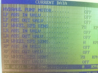
ABS live data:
When the vehicle is running at high speed:


The D.T.C:

This vehicle is front wheel drive. We jack it up on the hoist, the rear wheel can not turning as the front wheels, so there are no signal from both rear wheel speed sensors and create faults.
Actuator test:

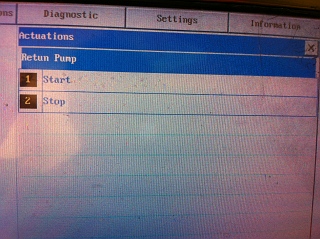
When we click the Start button for testing, we can hear the solenoid works, so this circuit should be fine.(The clicking sound from the video) We can test other circuit and actuator by the same way. But this is only for test electronic circuit or components, not for pressure, brake fluid, brake hose or anything else.
No comments:
Post a Comment