
The injector is a solenoid, when current flow through the coil, creates the magnetic field to open the injector and spray the fuel. The fuel injector is earth triggered, the battery voltage supply to the injector all the time, the signal from ECU switch on or off the transistor to close or open the injector circuit. If the battery voltage is low, the current in the solenoid is low, the magnetic field may not strong enough to full open the injector.
The circuit diagram of EFI

2. Reference Voltage at TPS sensor

The reference wire between ECU and TPS will cause the problem of the reference voltage.
If it short to ground, the reference voltage will very low.
If it open circuit, no reference voltage to TPS.
3. Ground at TPS sensor

If it is the bad earth, the total resistance in the TPS sensor will change, and the signal voltage should be wrong. See WS3A - Oscilloscope Patterns to Capture for detail.
The corrosion, bad connection, broken wires can cause the bad earth.
4. TPS sensor return/output
 |
| The throttle is closed, signal voltage is 0.370V |
 |
| The throttle is half way opened, signal voltage is 2.050V |
 |
| The throttle is fully opened, signal voltage is 3.67v |
The TPS works fine, no sudden jumps or gaps in the signal.
Idle swith:
 The colour of idle switch wire is Blue
The idle switch works fine. The battery voltage supply to the idle switch wire for this TPS. When the throttle is closed, the switch is closed and make a circuit to ground, so the voltage is low. When the throttle opened, the switch opened and the circuit opened to ground, so the voltage is battery voltage.
The principle of TPS sensor see Sensors - TPS for detail.
Bad earth, wrong reference voltage, the corrosion all can make the TPS signal out faulty.
The circuit diagram of TPS sensor:

5. TPS switches

The wire diagram of the TPS switch
 When the engine runs at idle, the battery terminal contact to idle terminal, so the voltage of idle is battery voltage and voltage of psw is 0V.
When the parts throttle cruise, PSW and Idle both no contact with the battery terminal, the voltage of them both are 0V
When wide open throttle, the battery terminal contact to PSW terminal, so the voltage of psw is battery voltage and voltage of Idle is 0V.
ECT (Engine Coolant Temperature) Sensor
The engine is warming up. The normal operation
 The reading of ECT sensor is 2.66V, the engine is still cold. The normal operating voltage of ECT should be about 0.5V.

 The ECT grond voltage is 0.02V less than 0.05V, it is good earth.
Bad earth will change the resistance of ECT to gives the wrong signal to ECU.
If the ECT has the bad earth, the signal voltage should higher than normal, see WS3A - Oscilloscope Patterns to Capture for detail.
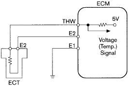
The circuit diagram of ECT:


Set multimeter to Hz scale and turn on the key:


The best way to measure the CMP signal is oscilloscope, because it is analog signal. If don't have oscilloscope, the measure Hz by multimeter, it tells you how fast the camshaft turning, measure the duty cycle, it tells you the percentage of the signal voltage is positive of negative.

The idle switch works fine. The battery voltage supply to the idle switch wire for this TPS. When the throttle is closed, the switch is closed and make a circuit to ground, so the voltage is low. When the throttle opened, the switch opened and the circuit opened to ground, so the voltage is battery voltage.
The principle of TPS sensor see Sensors - TPS for detail.
Bad earth, wrong reference voltage, the corrosion all can make the TPS signal out faulty.
The circuit diagram of TPS sensor:

5. TPS switches

Idle wire colour: Black
 |
| Volts at idle is 0.07V |
 |
| Volts at part throttle or open throttle is 10.78V |
 |
| Volts at open throttle is 0V |

When the parts throttle cruise, PSW and Idle both no contact with the battery terminal, the voltage of them both are 0V
When wide open throttle, the battery terminal contact to PSW terminal, so the voltage of psw is battery voltage and voltage of Idle is 0V.
ECT (Engine Coolant Temperature) Sensor
The engine is warming up. The normal operation


After a few minutes, the reading of ECT is 2.49V. That means the resistance of ECT is decreasing and engine is warmer than before.
The principle of ECT see Sensor - CTS for detail.
The ECT gives the signal to ECU let it know the engine temperature. If the temperature is low, the ECU will open the injector for longer to spray more fuel that warm up the engine until the engine reach the normal operating temperature.
Bad earth, corrosion of the wire or terminals, broken wires can make the ECT gives the wrong signal to ECU.
7. Ground Coolant Temperature Sensor

Bad earth will change the resistance of ECT to gives the wrong signal to ECU.
If the ECT has the bad earth, the signal voltage should higher than normal, see WS3A - Oscilloscope Patterns to Capture for detail.
The circuit diagram of ECT:

RPM Sensor or Crank Position Sensor (CKP)

The reading of the CKP is 0.29V (AC) at idle speed

Increase RPM to 2500 rpm, the reading is 0.56V (AC)

Change to DC volts, the reading is 0.568V (DC) at idle speed

Increase RPM to 2500 rpm, the reading is 1.08V (DC)

Change to read Hz, the reading is 503Hz at idle speed.

Increase RPM to 2500 rpm, the reading is 1539Hz.
The principle of RPM see Speed or Position Sensors for detail.
The best showed if RPM sensor was working is Hz. The signal of CKP is analog signal like wave signal. The different engine speed will change the frequency of the signal. The best way to measure the signal is using oscilloscope. But if oscilloscope is unavailable, then using multimeter to measure the frequency and duty cycle.
RPM sensor use to adjust the firing time, wrong sigal can cuase misfire and engine stall.
The circuit diagram of RPM:

MAP or MAF Sensor
MAP:

When turn the key ON, but don't start the engine, the reading of MAP sensor is 1.79V

When the engine at idle speed, the reading of MAP sensor is 0.39V
Short acceleration, the maximum reading of MAP sensor is 1.46V
The principle of MAP sensor see Sensor - MAP, MAF for detail.
The reading above is correct. When the engine is not running, the vacuum in the manifold is minimum, the reading should be the highest. When the engine at idle speed, the vacuum in the manifold in maximum, the reading should be lowest. When acceleration, the vacuum in the manifold decreased, the reading should be increased.
If the ECU get the wrong signal from MAP sensor, the injector open time will be wrong, the air / fuel ratio will be wrong, the engine will run rich or lean.
The circuit diagram of the MAP sensor:

MAF:
Check the terminals:
 |
| Pin 1 is temperature sensor voltage |
 |
| Pin 2 is battery voltage. |
 |
| Pin 3 is ground |
 |
| Pin 4 is reference voltage |
 |
| Pin 5 is MAF signal out |

The reading is 0 Hz
Start the engine, let it idle

The reading still 0 Hz.
Short acceleration:
The reading of MAF Hz increased.
The principle of MAF sensor see Sensor - MAP, MAF for detail.
The reading of this MAF is correct. When the key is on and running at idle speed, the air flow is stable and signal voltage is stable, so the frequency is 0 Hz. When short acceleration, the signal voltage changes so the frequency increase.
Wrong signal cause the same problem as MAP sensor.
IAT, ACT or MAT

The reading of IAT sensor is 3.21V. The reading is more than ECT before and shows IAT sensor is colder than ECT. Because IAT and ECT are both NTC resistor.
The principle of IAT see Sensor - IAT for detail.
Higher the air temperature, the reading of IAT is lower. Same volume of high temperature air contain less O2 atom than low temperature air. When the reading is high, means low temperature air, more O2 atom, so ECU control injector spray more fuel to reach 14.7:1 A/F ratio.
When the faulty signal is higher than normal, the mixture will be Rich.
When the faulty signal is lower than normal, the mixture will be Lean.
The circuit diagram of IAT:

Camshaft Position Sensor (CMP)
At idle:
 |
| DC voltage reading is 0.06V |
 |
| AC voltage reading is 0.4V |
 |
| Hz reading is 46Hz |
 |
| Duty cycle reading is 66.9% |
The circuit diagram of CMP:
No comments:
Post a Comment