| Signal Name | MAP VS Injector |
| Volt/Division/Range | 2V(MAP) 20V(injector) |
| Time/Division/Range | 5ms |
The pattern:

The wave A show the MAP sensor show there is no vacuum changing when the engine run at same RPM. For this pattern, MAP voltage is about 1.8V, that means the engine is running at high RPM, and injection fire should be longer than idling. For this pattern, wave B( injector ) open time is about 2.6ms.
When accelerate, throttle open more and decrease the vacuum in the manifold, so the MAP sensor signal voltage increase and let ECU to know more air is coming in. So ECU longer the injector open period for inject more fuel.
That means MAP can effect to injector open time but injector open time can not effect to MAP signal.
RPM against Injector
| Signal Name | RPM VS Injector |
| Volt/Division/Range | 10V(RPM) 10V(injector) |
| Time/Division/Range | 5ms |
The pattern:

RPM sensor sense the engine RPM. When accelerate, the injector open time increase and gives more power,so the engine rpm increase, sensor signal frequency increase and gives the signal to ECU to adjust the ignition timing.
Oxygen sensor against Injector
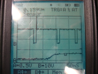
| Signal Name | O2 VS Injector |
| Volt/Division/Range | 0.5V(O2) 10V(injector) |
| Time/Division/Range | 50ms |
The pattern:
Ignition primary against Injector
| Signal Name | Ignition primary VS Injector |
| Volt/Division/Range | 20V(ignition) 10V(injector) |
| Time/Division/Range | 10ms |
The pattern:

Ignition primary voltage against Ignition primary current
| Signal Name | Ignition primary voltage VS Ignition primary current |
| Volt/Division/Range | 10V(voltage) 0.5v(current) |
| Time/Division/Range | 10ms |
The pattern:


The current clamp set to 20A(100mV/Amp). From the pattern, the maximum of current shows 0.45V, so the current should be 450mV / 100mV/Amp = 4.5A
The pattern shows when the ignition is dwell time, the primary coil connect to ground and make the close circuit, the current can go through the coil and built up the magnetic field. When the firing, the primary coil disconnect to ground and open the circuit, so no current in the circuit.
No comments:
Post a Comment